Concrete Bridge
Overview
The local chapter of the American Concrete Institute (ACI) is developing a concrete bridge competition in collaboration with the UNF ASCE Student Chapter.
Objectives
Students will act as Bridge Engineers to design a small scale concrete bridge to be used for vehicular travel (think hot wheels tracks). As Bridge Engineers, the goal will be to fabricate a safe and reliable bridge with serviceability, mass, strength, deflection, and ASTM standards in mind.
These goals include:
- Guaranteeing serviceability by accomodating two lanes of hot wheel tracks going opposite directions and meeting dimensional tolerances. These 2 lanes can be immediately next to each other or separated.
Ensuring bridge safety by meeting a minimum deflection (when load is applied at center span). Bridge deflection is an important parameter in safety examination of bridge structures. It reflects the overall stiffness of the bridge structure and is thus closely related to its bearing capacity and the ability to resist dynamic loadings such as traffic. In other words, bridge failure must not be sudden and without warning. Bridges should show signs of failure before ultimate failure, and thus should meet a minimum deflection.- Designing with efficiency and economy in mind, which is to build a structure for the lowest possible cost with fewer construction materials while providing a high level of functionality and safety. As Bridge Engineers, this means building the strongest and lightest bridge, which will require best engineering judgment with the design approach.
- Provide a high level of quality based on design criteria and code requirements. Teams will need to adhere to ASTM standards (for aggregate, cementitious materials, admixture, etc.) as well as submit a concrete mix design spreadhsheet to ensure industry compliance.
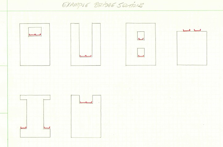
In order to encourage creativity and ingenuity teams must approach their design as if designing a real bridge for vehicle travel; taking inspiration from different bridges and design elements.
Eligibility
Each school is limited to 1 team of up to 5 undergraduate students
Materials and Limitations
CONCRETE BRIDGE
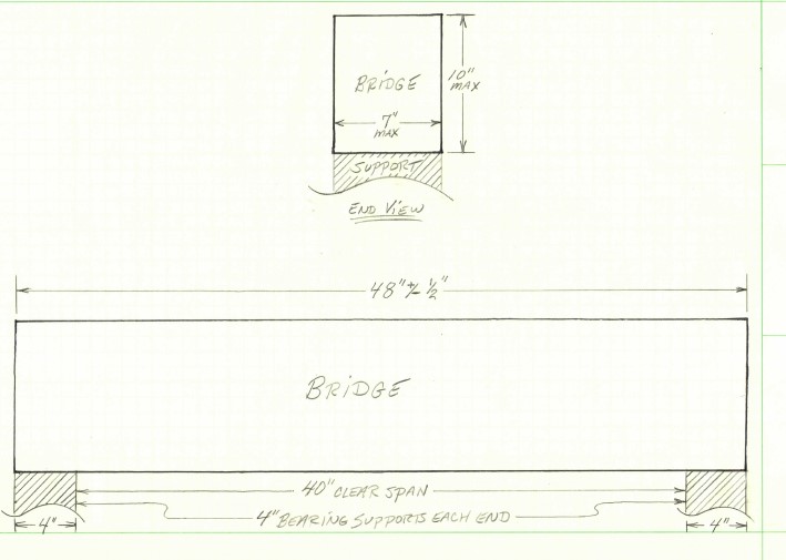
- Competing bridges are limited to a length of 4’ ± ½ in, a maximum height of 10” that includes the 2” minimum height per travel lane, and a maximum width of 7 in. Note: If the top of your bridge is a road bed, it means that the full height of your bridge must be 8” to account for the additional 2” height of the travel lane.
- Each bridge must accommodate for two lanes of Hot Wheels car traffic going opposite directions. Each lane must be at least 1.5 in. wide and have at least 2 in. height clearance.
- No other materials other than the concrete mix and fibers may be used for the construction and design of the bridge. No materials may be used to tie components together, other than approved adhesives to connect the roadbed/spacers to structural elements (i.e. trusses).
- Keep in mind during design that only the top of the bridge will be loaded, whether that be the truss or road. The load will be applied with a 7 x 7 in. loading platen at the center span of the bridge. Underneath the platen are 2 laterally placed steel rods with neoprene pads (spaced 6 in. apart). This is done to simulate industry standards. Note: Making the bridge smooth in this area will ensure uniform and correct loading.
- Bridges will be supported on either end with supports. Each support will be 4-inches in length. (updated 11/30/2022)
- The bridge must fit within the confines of a cuboid (rectangular prism) measuring 7” wide x 10” tall x
48”48.5″ long. However, the length cannot be shorter than the 40” clear span. (updated 12/23/2022, 1/19/2022) In loading, bridges must be able to meet a minimum XX 0.05″ deflection. When bridges reach a XXX 0.60″ deflection, loading will stop and be recorded. If the bridge breaks during loading, the deflection at failure will be used in scoring. If the bridge breaks during loading before reaching the maximum allowable deflection then that load will be recorded.
 The following guidelines shall be followed for design and fabrication
- Reinforcement of any kind is prohibited. i.e. Steel, Rebar
- Dimensional tolerances: 10 in. maximum height, 7 in. Maximum width, 4’ ± ½ in length
- The roadbed cross section (not including trusses) shall be consistent and uniform throughout the length of the bridge, and the ends of the bridge must be exposed.
- Synthetic Fibers meeting ASTM 1116
- Cement must meet ASTM C150, C595, and/or 1157
- Supplementary Cementitious Material must meet ASTM C618 or C989
- Normal Weight Aggregate must follow ASTM C33
- Lightweight Aggregate must follow ASTM C330
- Chemical admixtures must meet ASTM C494 and/or C260
- Adhesive must meet ASTM
TBAC881, Type I, Grade 1, Class C
MIX DESIGN
The mixture proportion (Mix Design) used for competition shall be submitted electronically before the symposium and no later than 11:59 PM EST on February 24. Failure to provide the mixture specifics will result in disqualification from the competition. Students are encouraged to submit mix design drafts and tentative bridge designs to jeffoleary1@comcast.net to ensure teams are on the right track towards fabricating an allowable bridge. The final submittal due by February 24th should be considered the final draft.
Note: Teams are not required to meet and are not limited to the number of material types listed. The following is an example of what that mix design spreadsheet should look like.
“Mix Design shall be proportioned to 1 cubic yard.”
cy = cubic yard
cf = cubic foot
cwt = hundredweight = 100 pounds
SCM = Supplementary cementitious materials
|
Material |
Type |
Proportions |
1. Quantity |
2. Specific Gravity |
3. Volume |
|
(lb/cy) |
(SSD) |
(cf) |
|||
|
Cementitious |
Portland Cement |
% of total Cementitious |
lb/cy |
||
|
SCM 1 |
% of total Cementitious |
lb/cy |
|||
|
SCM 2 |
% of total Cementitious |
lb/cy |
|||
|
SCM 3 |
% of total Cementitious |
lb/cy |
|||
|
Aggregates |
Aggregate 1 |
% of total Aggregate |
lb/cy |
||
|
Aggregate 2 |
% of total Aggregate |
lb/cy |
|||
|
Aggregate 3 |
% of total Aggregate |
lb/cy |
|||
|
Aggregate 4 |
% of total Aggregate |
lb/cy |
|||
|
Water |
Water |
N/A |
lb/cy |
62.4 |
|
|
Chemical Admixtures |
Admixture 1 |
oz/cwt |
oz/cy |
N/A |
N/A |
|
Admixture 2 |
oz/cwt |
oz/cy |
N/A |
N/A |
|
|
Admixture 3 |
oz/cwt |
oz/cy |
N/A |
N/A |
|
|
Admixture 4 |
oz/cwt |
oz/cy |
N/A |
N/A |
|
|
Fiber |
Fiber 1 |
N/A |
lb/cy |
N/A |
N/A |
|
Fiber 2 |
N/A |
lb/cy |
N/A |
N/A |
sum = 27 cf ± 0.02 cf
|
ADDITIONAL CALCULATIONS: |
|
|
Estimated Volume (ft3 ) |
mass of material/(specific gravity x 62.4) = volume |
|
Anticipated Density (pcf) |
= Weight / Volume |
|
Water to cementitious ratio |
= water weight / cementitious weight |
Tips
- Concrete Mix should be fluid/flowable (Self Consolidating Concrete)
- lightweight coarse and fine aggregate and/or air entraining agent will yield a lower mass, which is a primary component of the scoring.
- Supplementary cementitious materials can provide higher strength, which is a primary component of the scoring.
SUBMITTALS
Groups must submit their complete Mix Design along with a brief one (1) page report detailing the design and construction of the bridge. The report should include why the bridge design was chosen and describe the major steps in the construction process. The Mix Design and Report are due by February 24 at 11:59 pm EST.
Submit your Report and Mix Design to 2023sestudentsymposium@gmail.com with the subject line “Concrete Bridge Submittal – University Name”.
TESTING PROCEDURES
- Bridges will be loaded from the top down
- 7 by 7 in loading platen located midspan on top of the bridge
Judging and Scoring
|
Bridge Efficiency (Mass of Bridge / Load Until Failure) |
50 |
|
|
|
|
Bridge Mass *Smallest bridge mass receives the full 10 points. Largest bridge mass receives at least 1 point. All other teams will receive points based on linear interpolation. |
10 |
|
Bridge Load *Highest load receives the full 10 points. Lowest load receives at least 1 point. All other teams will receive points based on linear interpolation. |
10 |
|
Compliance with Materials |
|
|
Technical Report |
|
|
Total |
100 points |
Updates to the Rules
10/31/2022: Nothing spookier than a couple updates! Please see updates in the rules. Updates/changes/clarifications are marked with a strikethrough. Please not Judging and Scoring has updated to include new categories.
11/3/2022: Please see strikethroughs above – deflection is being removed from judging and scoring considerations, and points from that category have been re-distributed.
11/30/2022: Bridges will be supported on either end with supports. Each support will be 4-inches in length.
Competition FAQ
Comments (17)
Daniel Guerra
November 23, 2022 at 2:07 pmIs the bridge allowed to have spaced-apart columns underneith it throughout its length providing support?
Can the bridge have a continuous column underneith it throughout the bridge?
Or is the bridge only allowed to be supported by and touching the ground at its two ends?
nbohaczyk
November 30, 2022 at 5:58 pmIs the bridge allowed to have spaced-apart columns underneith it throughout its length providing support?
The bridge is to have a clear span. The bridge will rest only on the ends. The length of the support on the ends will be 4” each, which results in a clear span of 3’4”.
Can the bridge have a continuous column underneith it throughout the bridge?
A column is a vertical support and is not “continuous” along the bridge. If you are speaking of a column that rests on something (which is the purpose of a column), then no. the bridge is only supported on it’s ends.
Or is the bridge only allowed to be supported by and touching the ground at its two ends?
The bridge will be supported only on the ends. There will be nothing under it for support. The bridge below is supported on the ends with 4” long supports which rest on the ground.
Daniel Guerra
December 16, 2022 at 2:14 amWill the 4 inch supports in both sides be firmly attached to the ground?
Is the bridge allowed to push off of the 4 inch supports using the sides or is it only allowed to rest on top?
nbohaczyk
December 20, 2022 at 4:31 pmThe bridge supports will be firmly attached to the “ground”.
No, the bridge cannot push off. It must simply rest on the supports.
Daniel Guerra
December 21, 2022 at 1:40 amI have a question about the rules.
How is the load applied onto the bridge?
Below I have 2 interpretations of how the load is applied. Please tell me if either of them are correct or describe the loading the best you can.
For the load, it is my understanding that the load will be applied at 2-points, each point being 3 inches away from the center of the 7-inch plate. Because they are TWO-point loads instead of one distributed load, as long as my design is uniform on both sides of the center, I believe that the lateral pieces transferring the loads should rest onto and make contact with the structure at the same height on each side.
I spoke to someone that had a different interpretation of how the load will be applied. They said that I need to have a flat space of 7×7 in on top so that they can put their platen down that sits 6-in apart. The top of the bridge needs to be flat.
nbohaczyk
December 23, 2022 at 1:42 pmThe load will be applied via 2 bars, about 7” apart, at the center of the top of the bridge. The bars will extend the 7” width (or less if your bridge is less than 7” wide) of the bridge. The location does not have to be flat, however, if there is much deviation, especially between the 2 bars, the load may not be distributed evenly along both bars.
nbohaczyk
January 19, 2023 at 4:59 pmSome questions were received my an email. Please see a summary of these questions and responses below:
QUESTION 1:One of the rules states, “The roadbed cross-section (not including trusses) shall be consistent and uniform throughout the length of the bridge, and the ends of the bridge must be exposed.” Does this mean that an arch bridge cannot be used as a design?
ANSWER 1: An arch can be used, but if the road bed is on top, as I assume it would be, then the bridge can only be 8” tall. This would allow for the Hotwheel car clearance height of 2”, to keep the total height of bridge and car ≤ 10”.
QUESTION 2: Can you clarify what is meant by the ends of the bridge must be exposed? Can you provide an example of when it would NOT be exposed?
ANSWER 2: If the roadbed is within the structure of the bridge, it simply has to be able to accommodate the Hotwheel track and allow a car to roll completely through the length of the bridge. An example is a hollow “tube” but the ends are covered with concrete. The Hotwheel track has to pass through/on the entire length.
QUESTION 3: A rule for the materials states that the adhesive that can be used to connect elements of the bridge shall meet ASTM C881, Type I, Grade 1, Class C. Looking at the standard, I have found that this adhesive (Type I) is not meant to be used in load-bearing situations. Since this is likely to adhere, let’s say, a truss to the deck, and the truss is loaded; wouldn’t the adhesive need to be able to bear load in order to assist in transferring the loads between the structural components? Otherwise, I would consider it a weak link and the most likely place for failure to occur.
ANSWER 3: While the spec does say to meet Type I, the intent is a minimum of meeting Type I, we will allow the Type IV to be used.
QUESTION 4: Will the bridge be tested to failure (until it breaks)? I would believe so, but the rules do not explicitly say this since the deflection rule was dismissed.
ANSWER 4: It is certain the bridges will be loaded to failure.
QUESTION 5: One of the updated rules states, “The bridge must fit within the confines of a cuboid (rectangular prism) measuring 7” wide x 10” tall x 48” long. However, the length cannot be shorter than the 40” clear span. (updated 12/23/2022).” Later on, the rules state that the 48″ has a +/- 1/2″ tolerance. Can you confirm that this tolerance is still in place such that the confines will be 7″ x 10″ x 48.5″ in order to account for the maximum allowed length with the tolerance?
ANSWER 5: The length referenced in the cuboid dimensions should state 48 ½”. We would assume you will attempt to build the bridge to the target of 48” total length. However, construction is not precise so the ½” tolerance will help with your build. The end supports will be 40” apart, so any bridge with a total length shorter than 40” will not be tested.
QUESTION 6: Finally, out of curiosity, will hot wheels actually be used in the competition?
ANSWER 6: Yes, two tracks will be laid on/within the bridge and Hotwheel cars will be rolled the length of the bridge.
Aliyha
February 14, 2023 at 11:43 pmfor clarification to answer 1. Does the end of bridge to be taped off to be level with the surface of the end supports or can there be cut off with a drop?
nbohaczyk
February 22, 2023 at 4:12 pmRecommend that bridge ends are level with end supports to fit in testing device.
Artem
January 26, 2023 at 3:52 amHi! Is there a restriction on the length of the roadbed? (For example, in a true arch bridge, we can place the roadbed at different heights which changes its length)
Or the roadbed has to be equal to the span of the bridge?
nbohaczyk
February 7, 2023 at 3:34 pmThe road bed can deviate in elevation, but would have to meet customary road elevation changes, in proportion to the size of this bridge. It is strongly recommended that the design and elevation calculations be submitted for review.
Henry
February 2, 2023 at 8:51 pmAre metal fibers allowed?
nbohaczyk
February 7, 2023 at 3:32 pmNo, metal fibers will not be accepted.
Christopher R. Hernandez
February 3, 2023 at 12:22 amQuestion 1: Are we allowed to paint some details on the bridge?
Question 2: When writing the mix design do we have to specify the product and its brand or do we only have to specify the product?
Example: “2 oz of high range plasticizer” or “2 of Carlo’s 1430 high range plasticizer”
nbohaczyk
February 7, 2023 at 3:33 pmResponse 1: Yes, paint may be used.
Response 2: At a minimum specify the product. The brand of the product is encouraged, but not required, to document.
Anonymous
February 16, 2023 at 7:15 pmCan images/photos be in an appendix following the design report in order to provide clarification to the reader without exceeding the 1 page limit?
nbohaczyk
February 22, 2023 at 4:11 pmYes, that is okay.